Multi-Megawatt Generator Rental
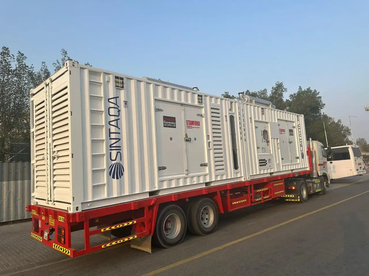
Synchronised plants built from new 1,250 kVA modules, from 2 MW to 10 MW and beyond, with standby units, MV step-up transformers, bulk fuel and O&M. Sized to your load, not to the nearest catalogue product.
- Per 1,250 kVA module at 0.8 pf
- ≈1 MW
- Standby modules for redundancy
- N+1 · N+2
- MV step-up where the load needs it
- 11 kV
- Whole plant set to one frequency
- 50 / 60 Hz
How do 1,250 kVA modules scale into a multi-megawatt plant?
Each 1,250 kVA module delivers about 1 MW. Several modules synchronise onto a common bus and share the load; one or two extra modules stand by for redundancy; a step-up transformer takes the bus to the MV voltage of the site. Capacity grows one module at a time, so the plant matches the load instead of a fixed product size.
- Required loadContinuous, peak and largest motor start
- Running modulesLoad ÷ planned kW per module
- Standby modulesN+1 or N+2 for availability
- Installed MVAAll modules × 1.25 MVA
- SynchronisationCommon bus, automatic load sharing
- DistributionLV switchboard or MV step-up
What does a 2, 5 or 10 MW temporary plant look like?
The engineering changes with size, not only the number of modules. As a typical engineering consideration, a 2 MW plant can often stay at LV, around 5 MW an MV connection is often the practical choice, and at 10 MW the MV design, fuel logistics and site layout drive the concept. The final design follows equipment data and the project load study.
| Load | Modules | Installed | Typical connection | Main engineering focus |
|---|---|---|---|---|
| 2 MW | 3 running + 1 standby | 5.0 MVA | LV, or MV if the network is MV | Cable sizing and LV busbar current (≈3,600 A at 400 V) |
| 5 MW | 7 running + 1 standby | 10.0 MVA | MV via step-up transformer | Transformer sizing, MV switchgear, protection coordination |
| 10 MW | 13 running + 1 standby | 17.5 MVA | MV, often several transformer groups | Plant layout, fuel logistics, MV switchboard, power management |
| Load | At 400 V | At 11 kV |
|---|---|---|
| 2 MW | ≈3,600 A | ≈130 A |
| 5 MW | ≈9,000 A | ≈330 A |
| 10 MW | ≈18,000 A | ≈660 A |
01 — CONFIGURATOR
Temporary power plant configurator.
Indicative only — final configuration requires engineering review.
- Running modules
- 7 × 1,250 kVA
- Standby (N+1)
- 1
- Installed capacity
- 10 MVA
- Load per running module
- ≈71%
- 7 synchronised modules carry the load, 1 more stands by for N+1. All modules connect to a common synchronising bus.
- Connection at 11 kV: step-up transformer capacity for at least 8.75 MVA of running generation, plus MV switchgear and protection.
- Diesel at 24 h/day: estimated 30,000–32,400 litres per day. Guaranteed specific fuel consumption is 0.21–0.25 kg/kWh (25–100% of prime rating); actual total daily fuel volume depends on the actual electrical load, operating hours, load profile, ambient conditions, generator configuration and project operating conditions; daily estimates on this site use 0.25–0.27 L/kWh, the 50–100% load part of the guaranteed range. Bulk tank size follows delivery frequency and site access.
Illustrative planning assumptions: 1,250 kVA ≈ 1,000 kW at 0.8 power factor, the planned loading you selected, and the peak covered at full rating. Not checked here: largest motor start and starting method, transient steps, harmonics, ambient temperature and altitude derating, fault levels and protection. Our engineers check these before we quote.
How much fuel storage does a multi-megawatt plant need?
SINTAQA guarantees a specific fuel consumption of 0.21–0.25 kg/kWh (25–100% of prime rating). At a steady 5 MW around the clock that is an estimated 30,000–32,000 litres per day, so bulk storage is sized to the delivery schedule and to how many days the site must run if a delivery is late.
| Average load | Litres per day | Days from 68,000 L of storage |
|---|---|---|
| 2 MW | ≈12,000–13,000 | ≈5.2–5.7 |
| 5 MW | ≈30,000–32,000 | ≈2.1–2.3 |
| 10 MW | ≈60,000–65,000 | ≈1.0–1.1 |
On island and remote sites, fuel autonomy often decides the tank count more than the generator count. See the Dalma Island case study.
What limits the size of a temporary plant?
Site footprint, fuel logistics, the MV connection and equipment availability. The modular concept itself does not cap the size. For long contracts, generally from 12 months, SINTAQA procures a dedicated fleet for the project, so large plants are not limited to units already in stock.
Multi-megawatt rental: FAQ
How large can a modular temporary power plant become?
There is no fixed ceiling in the modular concept: plants grow in steps of one 1,250 kVA module, about 1 MW. In practice size is limited by site footprint, fuel logistics, MV design and fleet availability. For long contracts, generally 12 months or more, SINTAQA procures additional units for the project.
Should a 5 MW plant connect at LV or MV?
Often MV, but it depends on where the load is connected. At 400 V and 0.8 power factor, 5 MW means around 9,000 A, which needs very large busbars and many parallel cables; at 11 kV the current is about 330 A. The connection voltage is decided in the project design.
How much diesel does a 10 MW temporary plant use?
An estimated 60,000–65,000 litres per day at a steady 10 MW around the clock. Guaranteed fuel consumption for SINTAQA 1,250 kVA units under the specified operating and load conditions is 0.21–0.25 kg/kWh (approximately 0.25–0.30 litres per kWh): between 25% and 100% of prime rating at 50 Hz, with the fuel specification and site conditions stated in the quotation. Actual total daily fuel volume depends on the actual electrical load, operating hours, load profile, ambient conditions, generator configuration and project operating conditions; daily estimates on this site use 0.25–0.27 L/kWh, the 50–100% load part of the guaranteed range.
Is N+1 enough for a multi-megawatt plant?
N+1 is a common configuration for many temporary-power applications, but the required redundancy is determined by load criticality, the consequence of an outage, the maintenance strategy and the client's project requirements. Critical loads, long unmanned periods or servicing units while the plant runs may justify N+2.
Technical content prepared and reviewed by the SINTAQA Engineering Team, Dubai. Last updated September 2026. Configurations shown are indicative; every project is engineered to its own load, site and standards.
Request a multi-MW plant proposal
Send the load, voltage, frequency and duration, or a load schedule. We will return a configuration, single-line concept and commercial offer.